So, the board is assembled and programmable over JTAG. Next step is testing functionality of the rest of the board. I wanted to do this with MicroPython, and I made sure to get an MCU with enough flash, but it turns out there isn't a MicroPython port for my MCU (STM32G0B0KET6), even though it has enough flash. Whoops. Live and learn.
In fact, all the MicroPython ports are for existing dev boards, mostly NUCLEO dev boards. Probably if you want to use it on your own board, you need to write your own board. Ugh. MicroPython seems a little worse now.
Looks like I'll just be using STM32 HAL.
The first problem was the INA700 not responding over I2C
Pulled out the oscilloscope and checked what's happening on the lines, and the lines are never going high.
Oops, I forgot to enable the MCU's internal pull-ups on those pins.
Fixed that in STM32CubeMX, regenerated the code, and I can read registers from INA700 now.
Next weird thing: comparison of expected and real data always succeeds, even when they don't match. This is the source for my basic I2C connection test:
// A0->GND therefore addr is 1000100 = 0x44
#define INA700_ADDR ((uint8_t) 0x44 << 1)
#define INA700_ADC_CONFIG_REG ((uint8_t) 0x01)

uint8_t send_data[] = {INA700_ADC_CONFIG_REG};
HAL_StatusTypeDef status = HAL_I2C_Master_Transmit(&hi2c2, INA700_ADDR, send_data, sizeof(send_data), 10000);

if (status != HAL_OK) {
  Error_Handler();
}

uint8_t expected_recv_data[] = {0xFB, 0x67}; // really should be 0x68
uint8_t real_recv_data[sizeof(expected_recv_data)];

status = HAL_I2C_Master_Receive(&hi2c2, INA700_ADDR, real_recv_data, sizeof(real_recv_data), 10000);

if (status != HAL_OK) {
  Error_Handler();
}

if (memcmp(expected_recv_data, real_recv_data, sizeof(real_recv_data) != 0)) {
  Error_Handler();
}
Inspecting real_recv_data and expected_recv_data before the
memcmp reveals that they are different:
(gdb) p/x real_recv_data
$9 = {0xfb, 0x68}
(gdb) p/x expected_recv_data
$10 = {0xfb, 0x67}
However, step brings us down past the if to the final while (1) {} at the end of main, indicating the condition has failed. What's
going on here?
The assembly following a break on the if (memcmp... line is:
(gdb) x/10i $pc
=> 0x8000574 <main+80>:	add	r3, sp, #12
   0x8000576 <main+82>:	ldrb	r3, [r3, #0]
   0x8000578 <main+84>:	cmp	r3, #251	@ 0xfb
   0x800057a <main+86>:	bne.n	0x8000582 <main+94>
   0x800057c <main+88>:	b.n	0x800057c <main+88>
   0x800057e <main+90>:	bl	0x8000400 <Error_Handler>
   0x8000582 <main+94>:	bl	0x8000400 <Error_Handler>
   0x8000586 <main+98>:	nop			@ (mov r8, r8)
   0x8000588 <main+100>:	adds	r0, r4, #5
   0x800058a <main+102>:	lsrs	r0, r0, #32
Aha! It's only comparing the first byte of the array. But
sizeof(real_recv_data) is 2...
Aha! Misplaced parenthesis. sizeof(real_recv_data) != 0)) -> sizeof(real_recv_data)) != 0) It's always something
foolish. That's that figured.
LEDs worked with no problem. Only needed these two lines in a while loop:
HAL_Delay(1000); // 1000 ms
HAL_GPIO_TogglePin(LED_R_GPIO_Port, LED_R_Pin);
First I realized that STM32CubeMX had not generated any ISRs, so I needed to reconfigure the pin from GPIO_Input to GPIO_EXTI8.
After rerunning codegen I created two callbacks for falling and rising cases:
void HAL_GPIO_EXTI_Rising_Callback(uint16_t GPIO_Pin) {
  HAL_GPIO_TogglePin(LED_R_GPIO_Port, LED_R_Pin);
}

void HAL_GPIO_EXTI_Falling_Callback(uint16_t GPIO_Pin) {
  HAL_GPIO_TogglePin(LED_R_GPIO_Port, LED_R_Pin);
}
And observed that button presses and releases toggled the LED.
This is the big one, this is the main original thing that the board was made to do.
Check.

HAL_GPIO_WritePin(EN_5V_GPIO_Port, EN_5V_Pin, GPIO_PIN_SET);
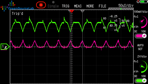
Oh no! We're getting some sort of sawtooth-ish waveform on the input and output of the load switch. Period is about 50 us, so 200 kHz.
For half of the period, input is flat at 5.2V and output is flat at 0V. For the other half, the input is a downward sawtooth to 3.2V and the output is an upward sawtooth to 80mV.
Whew, that actually gets quite hot!
There's also a small disruption on the 5V_EN line, but not much:
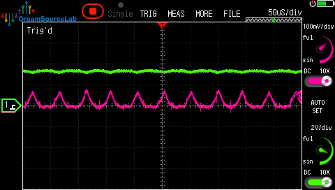
As I began hooking up the oscilloscope to observe the ST pin, I realized that my oscilloscope ground clip was shorting Vout to GND. Grounding the scope in a better place fixed the issue. What was happening was the over-current protection was getting triggered over and over.
How long does it take for a switch to happen? The slope is about 40 us long.
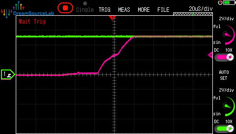
That's all the basic functionality validated, we've got a good board!
Please send comments to blogger-jack@pearson.onl.