In my last post, I laid out how I evaluated two multiplexing methods: Diode-Protected and Capacitor-Smoothed. And I found that with the load switch I was using, the Diode-Protected method was the only feasible method.
However, after talking with an experienced electrical engineer, I learnt that that method is infeasible for thermal reasons. I was planning to ignore thermal issues until they cropped up on their own. But with some quick back-of-the-napkin math, one can quickly see that the Diode-Protected method will not work.
Here's how.
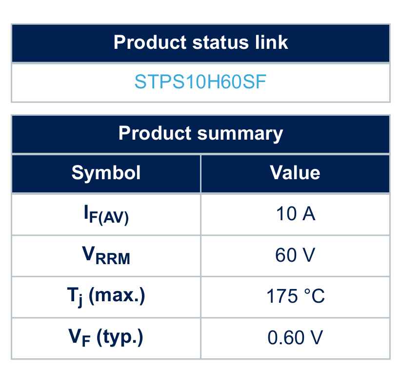
I'm running up to 10A through stps10h60sf. At 10A, it has a 0.6V voltage drop:
That means 6W power used by the diode.Then we have to translate that into a temperature rise using this thermal resistance vs footprint size:
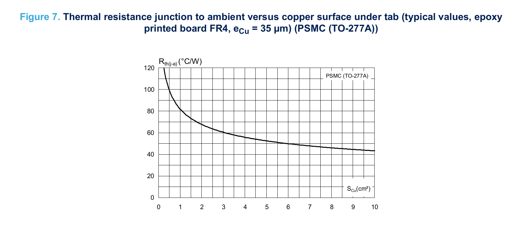
The details of thermal metrics are explained in this TI AN. But all we need to do looking at this graph is take the best case value for RTH(j-a) and multiply it by the power to get temperature rise.
40 °C/W * 6W = 240 °C. That will melt most solders.
This diode simply cannot be along the main power path.
One option is the back-to-back MOSFETs idea outlined in "Future Work" in my last post. This provides reverse-current protection and very low Rds so that the thermal issue is avoided.
Each rail would have a gate driver for the back-to-back MOSFETs. Either using a premade solution like UCC23313 or using an opamp as a custom gate driver to drive the back-to-back MOSFETs. The custom opamp is cheaper and has lower quiescent current (300uA vs 1.2mA).
I can make it so that only the driver for the currently active rail draws quiescent current by disabling the supply to the inactive opamps and instead pulling each back-to-back MOSFET gate net low using another NMOS.
In this configuration, the whole multiplexer wastes at least 300 uA * 24 V = 7.2 mW, which seems awesome. BoM cost per rail with opamp solution on the slave board @ 100 quantity would be something like $0.44 for STL36DN6F7 + $0.04 for LM2904BIDR + $0.11 for NTJD5121NT1G = $0.59.
I would need to run a SPICE simulation and make a prototype to figure out how feasible the approach is though. I'm somewhat worried about complications discussed in the answers to this electronics SE question, but I think that they can be avoided with N-MOSFETS connected with common source, as shown in the interior of the LM7310 load switch in its simplfied schematic on its datasheet.
And of course there's the question of whether the switching speed is accepable.
The Back-to-Back NMOS method is prima facie feasible, but I would need to run some simulations and make a prototype to be sure.
Or I could revisit the humble relay. I discarded latching relays because they were too expensive, and that hasn't changed. I discarded non-latching relays because they drew too much power at rest. It takes 360mW to keep closed an N.O. relay like the J1071AS line from CIT relay & switch.
With 10 modules you're looking at 3.6W wasted, which is actually pretty tolerable.
The footprint would be rather large for 6 relays. Each one is 1.54 cm x 1.9 cm, so in a 2 x 4 grid you're looking at 3.8 cm x 4.62 cm = 1.5 in x 1.81 in.
Which is just barely reasonable.
However, there is a 10ms switch time. A 10ms switch time would require a lot of capacitance on the load to smooth out to 0.1V drop with even 3A load. (3A * 10ms / 0.1V = 300 mF).
Which actually doesn't matter if user plans to configure output to correct voltage then connect device. It is a problem for USB-PD, where the USB-PD spec requires that voltage transitions don't ever drop below the starting voltage on an upward transition.
Cost-wise, relays are pretty nice. The J1071AS line is $0.40 per unit @ 100 quantity, and the NPN probably $0.05 resulting in total per-rail cost of $0.45. A decent amount cheaper than Back-to-Back N-MOSFETs.
Non-Latching Relays are infeasible for USB-PD due to switch time, but they are feasible for plain DC outputs in spite of footprint and quiescent current disadvantages.
And of course the eternal option, a simple mechanical slide switch.
Design would be very simple, and cost low. A 6-position slide switch is $1.15 on DigiKey @ 100 quantity. Slide switches do not seem to come in more than 6 positions, but happily 6 rails is all I'm targeting for now.
Slide switches are really the best option of the switch options on offer. The cheapest 6-position rotary switch is $4.62, and selector switches even more expensive. They also cap out at about 6 positions.
The problem with a simple DIP switch design where each switch enables or disables a rail would allow the user to short two rails together when he enables two rails at a time.
However, a more clever design, where each DIP switch acts as a bit in multiplexing the input, could work quite well and prevent him from ever shorting two power rails.
For example:
                                  ---- 20V
                                 /
                        ----- SW2
                       /         \
                      /           ---- 12V
GND --- LOAD -- SW1 --
                      \           ---- 9V
                       \         /
                        ----- SW2
                                 \
                                  ---- 5V
This is a little more complicated for the user, but so long as he can look at the current voltage level on that module using the display on the master board, he should be able to figure it out.
However, because I don't need more than 6 rails, I will not consider this design further now, instead filing it away in case I need it later.
I will also need the ability to turn the input on and off from the MCU for OCP. This could be done with an NC power relay. Or footprint could be reduced with a custom back-to-back NMOS circuit as outlined earlier.
This would also allow for remote toggling of connected devices for "smart power strip"-like functionality.
The Slide Switch approach is superior in cost and footprint to the Non-Latched Relay approach and the Back-to-Back NMOSFETs approach for Simple DC modules. It is obviously infeasible for the USB-PD module
I could drop USB-PD support entirely from my design. An Amazon search for "500W USB-PD power supply" reveals some very reasonably priced results (although I'm a little skeptical of whether they can really deliver the output they claim). The user could just use one of those instead. In fact, I could include in the case of this product a place to put one of those and plug it in, having just the USB cords coming out.
And dropping USB-PD doesn't totally preclude USB power modules; I could still make one that supplies the standard 5V output very easily. It would just be a USB port with the power lines connected to the 5V rail and data lines disconnected.
Alternatively, I could use a different multiplexing circuit for USB-PD and simple DC modules. I hoped to avoid doing this to simplify the design process, but considering that USB-PD support is proving so onerous, it seems prudent to keep that complexity off of the Simple DC modules.
For the USB-PD modules, I can drop the 10A requirement down to 5A, as that is all that is asked by the spec, excluding USB PD Extended Power Range.
This means that I can use a TI load switch! The LM7310 supports 23V and 5.5A, and it uses back-to-back NMOSFETs internally. As only four voltage levels are needed by USB-PD and the part is $0.62 @ 100 quantity, totaly cost for multiplexing circuit would be $2.48. Quite good. Although whether the switching speed would be sufficiently fast remains an open question.
Another option is putting a voltage regulator on each USB-PD module. I discarded the idea of doing this on the simple DC modules for cost reasons, but there's not reason why I couldn't make "premium" USB-PD modules. They could cost more like $20 apiece rather than $5.
I am going to drop USB-PD support for now due to complexity of support with this design. I will design a module with a slide switch to select the power rail.
I'm getting a sense of what the "API" of each slave board should be: get power, get voltage, and enable-disable, and recieve "select me" SMBAlert from button.
Please send comments to blogger-jack@pearson.onl.