If you're studying switching power supply topologies, perhaps from this TI application report, you'll soon come across the flyback topology. Buck, boost, and buck-boost topologies can be understood with the simple analogy of an inductor as a flywheel. However the flyback topology requires a bit deeper knowledge. Faraday's law, Lenz's law, and the working principle of transformers (which I refreshed using this video on YouTube from The Engineering Mindset.
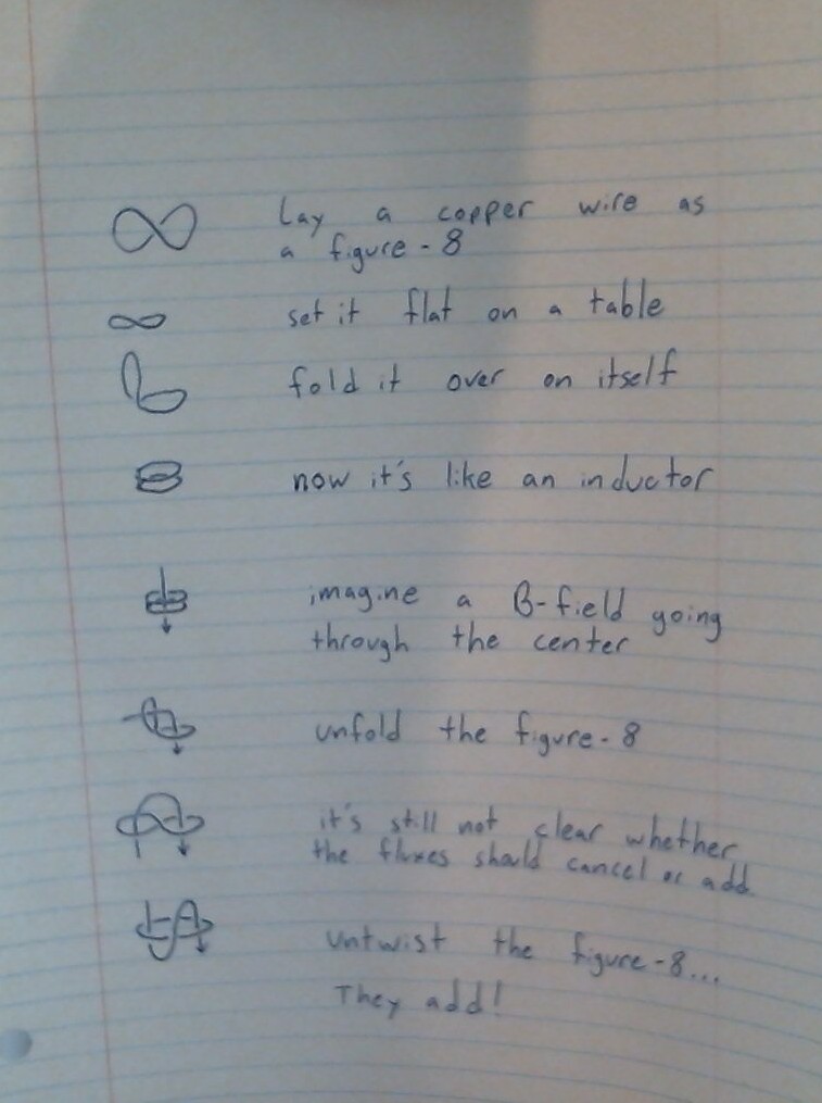
But that explanation leaned on a certain implicit model of inductors which didn't quite comfortably in my mind, and maybe it doesn't with you. In a transformer, sure you have the B-field going through several coil loops, the number of which determine the voltage ratio. But who's to say that those many passes through the coils don't all boil down to one or cancel in some way when you unwrap the coil?
I made this little sheet to understand why not.
Please send comments to blogger-jack@pearson.onl.