Buck regulators are a pretty simple thing when you get down to it: a PWM signal put through a bandpass filter which gets you a nearly-DC output. But not quite. There is ripple on the output. And one of the things you do when you design a buck regulator is decide acceptable values for your inductor current ripple and output voltage ripple.
Inductor current ripple is calculated with this equation (per this AN):
ΔIL = (VIN - VOUT) * D / (fSW * L)
Convert frequency fSW to period tSW then divide both sides by D*tSW, and you find that it's a conservative approximation of the equation for current in an inductor:
ΔIL / (tSW * D) = (VIN - VOUT) / L
Now, I'm using the APM81911 which is integrated-inductor. So they actually don't provide that equation in the datasheet nor any other way to estimate ΔIL. Obnoxious. However, that TI AN says that 20% to 40% out output current is a decent guess. Seeing as the module is rated for 3A, I'm going to assume 1.2A inductor current ripple.
What does this mean for capacitor selection? It would be used in this huge Equation 5 in the datasheet for getting an equivalent ESR, ESL, and C which reduce voltage ripple to a certain amount. However, the terms are such that voltage ripple is driven to zero with zero ESR and ESL (accomplished with a ceramic capacitor) and capacitance is driven very high (accomplished with an electrolytic capacitor).
They describe considerations for what to do if you're only using ceramic or only using electrolytic capacitors. However, you can use both, and I actually did so successfully on the TPS55288 eval board. So the plan is to use a ceramic capacitor, with room to add a larger electrolytic if I need.
And actually, some back-of-the-napkin math indicates that I can get away with only 5uF or so on the output. And I already have some ceramic caps going up to 22uF. So maybe I can get by with just ceramic caps I already have. But ceramic capacitors derate significantly with bias voltage, so I'm going to need to run a couple of experiments on the bench see if they'll really work.
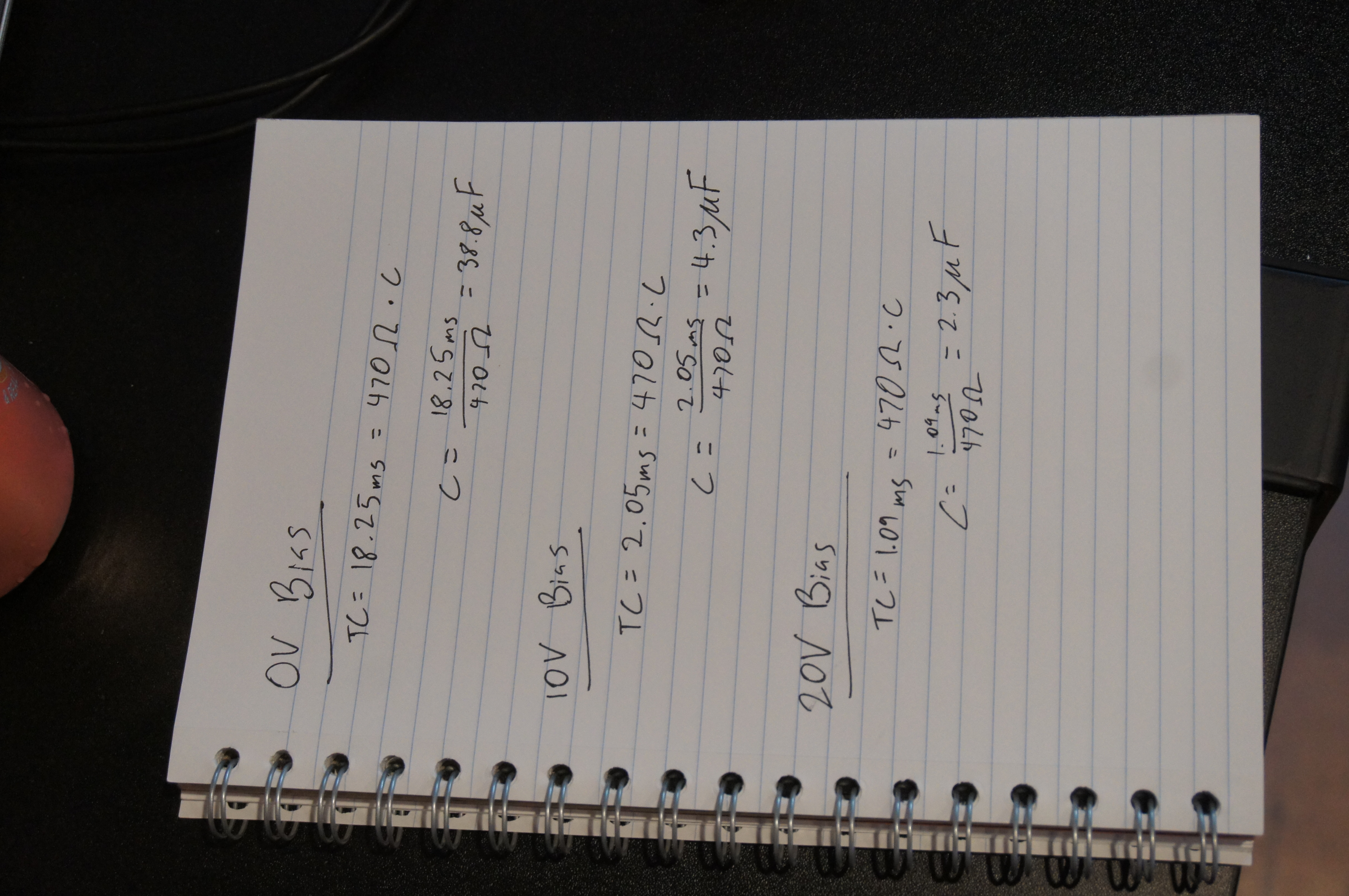
Ran those experiments. The findings:
It derates to 4uF at 10V bias and 2uF at 20V bias!
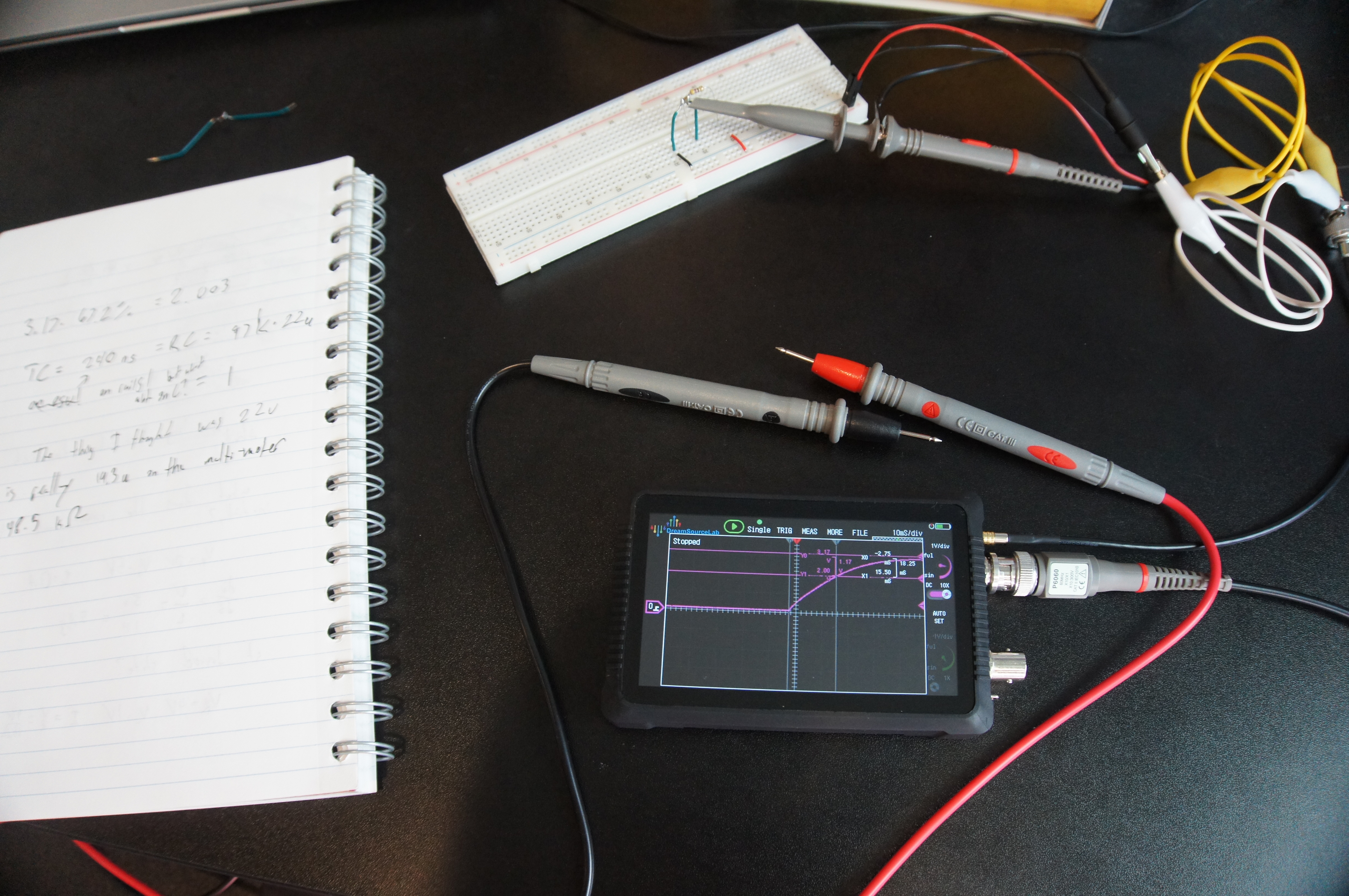
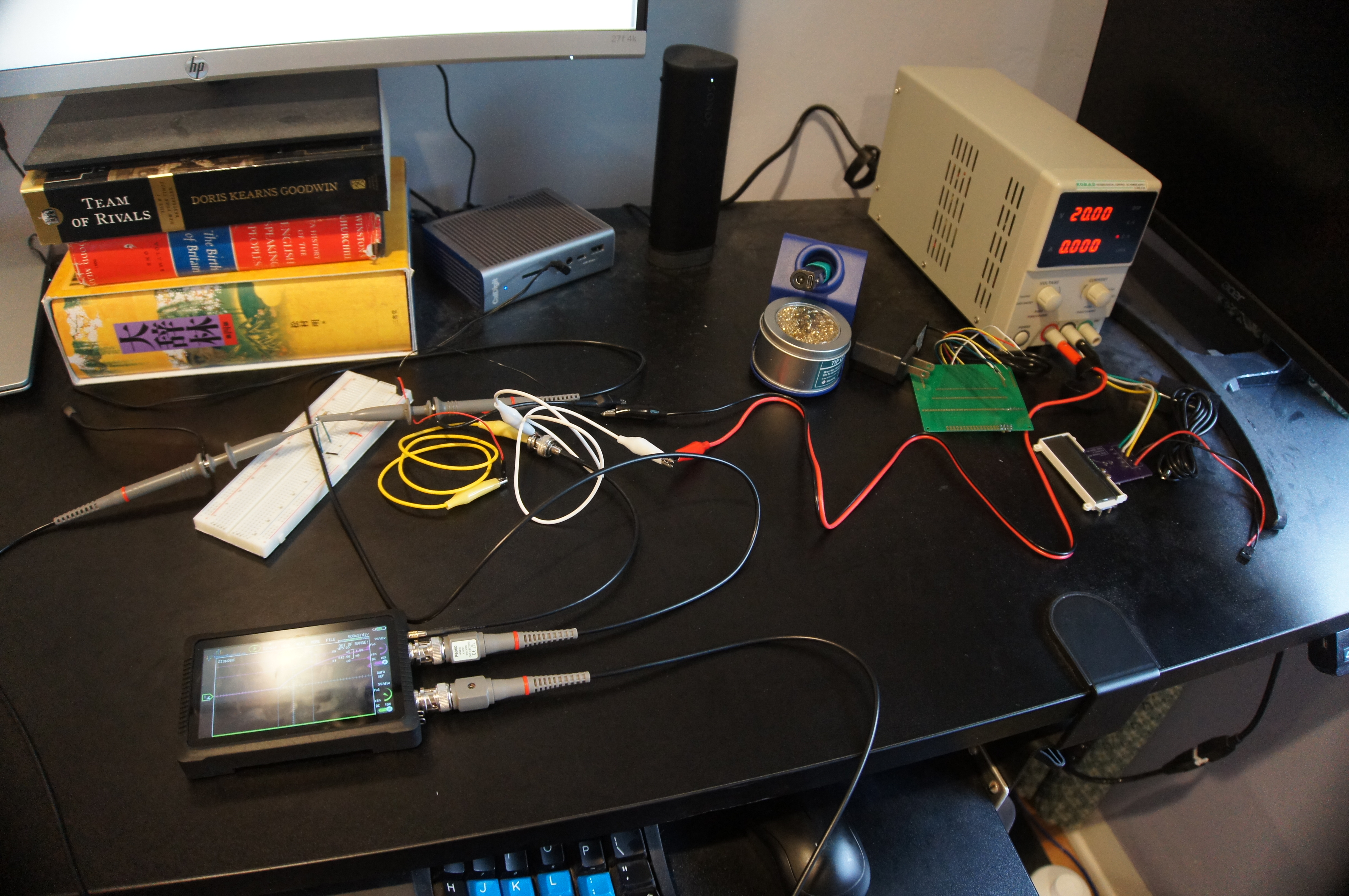
This was my setup:
And the measurements:
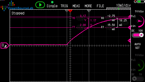
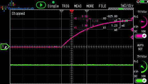
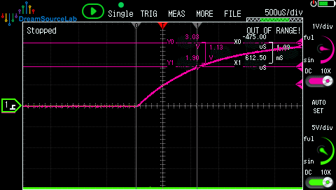
Since my signal generator is built into my oscilloscope and they share a ground, I had to make all my measurements relative to the negative end of the signal generator which was connected to the positive terminal of the power supply. Hence the bias reading negative even though it was positive.
I'll look into getting some better ceramic caps. And make space on the board for attaching multiple ceramic and electrolytic caps so I can play with it and get it right.
Please send comments to blogger-jack@pearson.onl.